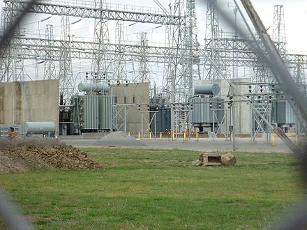
A 220/132 KV Grid Substation means that input voltage in the substation will be 220 Kilo-volts(KV) and the transformer installed in the substation will step down this voltage to 132 kilo-volts(KV) for onwards transmission. Usually there will be two separate switchyards of 220kv and 132kv voltage level and equipment of corresponding voltage levels like CVT,C.B,C.T, L.A,Bus-bars etc are installed in these switchyards.

(PC-Wikipedia)
There are also 220/132/33 KV Grid Substations which means that Input voltage in the Substation is 220kv and two output voltages 132kv and 33kv are obtained either using separate 220/132kv and 132/33 kv step-down transformers or both 132kv and 33kv voltage level can also be obtained using a single Autotransformer as it also has a tertiary winding for stepping down 132kv voltage level to 33kv. We can use output of tertiary winding to give power to 33kv feeders .
220/132 kv Grid Substation differs from 132/33kv Substation mainly in following aspects:
(i) In 220/132 kv Grid Substation and above voltage level substations we use Auto transformers
Why do we use Autotransformer in 220/132 KV Grid Substation and at higher voltage levels?
Let us understand first what is an Autotransformer and how it differs from conventional transformers?
a) Conventional transformers have two windings -Primary and secondary but an Auto-transformer has just single winding which is wound around a laminated core. The auto-transformer works on the principle of self-induction ,on the other hand the conventional transformer works on the principle of mutual induction i.e When two coils are brought in proximity to each other, the magnetic field in one of the coils tends to link with the other which in turn leads to the generation of voltage in the second coil.

Desired secondary voltage is obtained by tapping at particular points in an Autotransformer as shown in the above picture. Compared to two winding transformers as Autotransformer has only one winding therefore Autotransformers have the advantages of being smaller, lighter, and cheaper (due to less copper being used) than typical dual-winding transformers, but there is also disadvantage that there is no electrical isolation between primary and secondary circuits.
Other advantages of Autotransformers include lower leakage reactance, lower losses, lower excitation current, and increased VA rating for a given size and mass. Power Transfer in Autotransformer is done Partly by transformation and partly by direct electrical connection.
b) Other than cooling fans ,Autotransformers are cooled using oil circulating pumps which circulate the oil from radiators to the main body.
c) Autotransformers also have a tertiary winding . The tertiary winding are used because they can effectively reduce the overall zero-sequence impedance and therefore reduce the overvoltage problem during a ground fault.
d) The starting current of the auto-transformer is less than the actual current, whereas the starting current of the conventional transformer is one-third of the main current.The auto-transformer is more efficient as compared to the conventional transformer.
Due to above mentioned reasons Autotransformers are preferred at higher voltage levels.
(ii) In 220/132 KV Grid Substation IPS tubes are used in the bays in place of ACSR conductors
IPS( iron pipe size ) tubes are cylindrical bus tubes where the current is carried through AL / Cu tubes which are hollow inside while ACSR conductor are simply conductors with no any hollow part inside.
To understand its advantage over ACSR conductor lets understand following points :
a) At higher voltage level as more current flows in the line/transformer bays ,therefore use of bundled conductors using spacers and connectors is avoided in the bays ,because to support four (quad) or more conductors we will need many clamps and connectors which will make the system bulky and it can create operational issues also there can be considerable sagging of conductors which is not desired.
b) Skin effect– A/C current does not flow uniformly across the cross section of the conductor. The tendency of A/C current to flow more on outer surface and very less in inside part of conductor is called Skin effect. IPS Bus tubes are hollow inside which significantly mitigates the skin effect , also as they are solid metal tubes they don’t create any sag ,they are suspended on post insulators.
(iii) In 220/132 KV Grid Substation We use Two main bus systems :
In 132/33kv Sub-stations we normally use One Main bus and One transfer bus scheme but to increase more operational flexibility and more power flow Two main bus (Main bus-01 and Main Bus-02) and one transfer bus system is used in 220/132 kv grid substations.

Breaker and a half scheme and or double main and transfer bus scheme can be implemented for higher voltage levels. As we can see from the above pic that scheme shown uses two main buses, and in each circuit two bus isolator switches have been provided, thus any feeder/bay can be connected with Bus-01 , Bus-02 or both. A bus-coupler circuit is also provided to connect the two main buses with each other, thus it allows the flexibility to transfer a feeder from one bus to the other bus without any need of deenergizing that particular feeder circuit by simply operating the isolator switches.
It is to be noted that as bus P.T is used in the main bus ,therefore two sets of P.Ts for each bus is used in this scheme.At one time, input supply from one P.T is taken ,it is done using a voltage selection relay. Voltage selection relay makes automatic connection of metering equipment to an alternative supply if the normal or preferred supply fails.
Thus ,other than providing operational flexibility the above scheme gives advantage of maintenance of bus without power interruption.
(IV) Fire hydrant System in a 220/132 KV Grid Substation
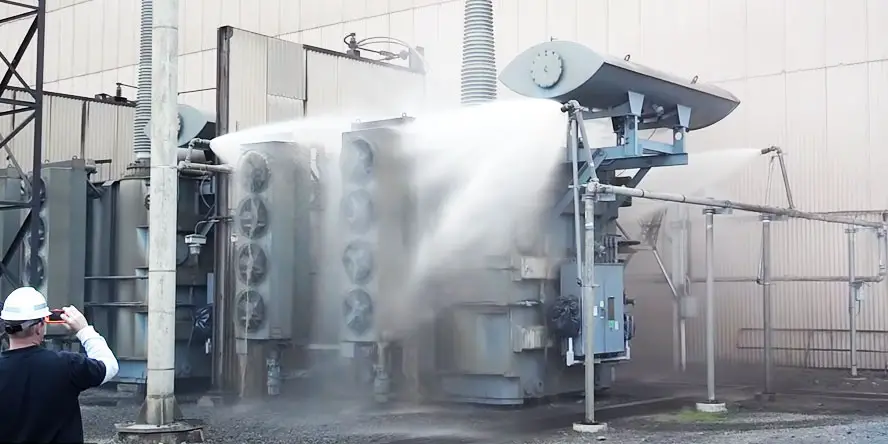
As transformers installed in a 220/132 kv grid substation is of higher rating (typically more than 100MVA) , chances of fire also becomes a point of concern .Fire in high voltage power transformers can be very difficult to extinguish using DCP or Co2 based fire hydrants ,therefore water sprinkle system is installed over the power transformers.

A pump house with water storage tank is constructed for this purpose in the substation and the outlet pipes are run all across the switchyard and near important places as desired and also near the power transformers from here pipes are connected with the sprinkling system installed on the power transformers.
Water Pipes with sprinklers are installed all around the transformer and heating sensors at various points are also installed in them. Due to fire in the transformer when temperature goes up ,the sensors get actuated and water is sprinkled from all sides to extinguish the fire.
All other equipment in a 220/132 kv Grid Substation like CT,CVT,breakers, bus-bars,L.A etc will remain same as in 132/33kv substation, except that they will differ in their ratings.