Introduction
Electric drawing of metering circuit in a control panel refers to the electrical circuitry and components designed to measure various electrical parameters within a system or equipment. This circuit plays a crucial role in monitoring and managing the electrical characteristics of the system. Here are some key points to understand about a metering circuit in a control panel.
Purpose of Metering Circuit
The primary purpose of a metering circuit is to measure and display important electrical parameters, such as voltage, current, power, frequency, and sometimes energy consumption. This information is vital for monitoring the performance of electrical systems, ensuring safety, and making informed decisions regarding system operation and maintenance.
Components of a Metering Circuit
A typical metering circuit includes various components, such as current transformers (CTs) and potential transformers (PTs) to step down high-voltage and high-current signals to levels suitable for measurement. These transformed signals are then processed by meters, relays, or other monitoring devices.
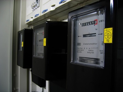
Measurement Devices: We may find a variety of measurement devices, including digital or analog meters, power quality analyzers, and energy meters. These instruments are responsible for displaying the measured parameters in a user-friendly format.
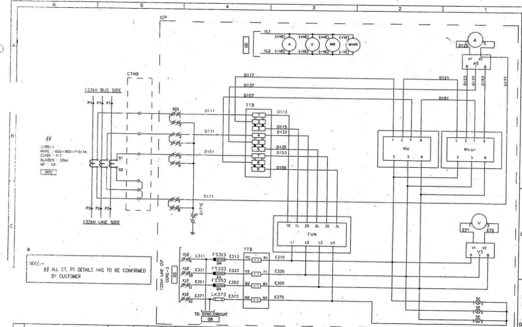
Electric Drawing of Metering circuit (Three phase energy meter) indicates the C.T and P.T connection in an energy meter , a trivector meter (TVM) is used in substations for metering purpose.
This meter is installed in the Control panel. In the metering circuit connection drawing shown below , various acronyms have been explained as following:
TTB (Test terminal blocks): These are terminal blocks available on Control & relay Panel from where CT/PT connections are made.
CTMB-Current transformer Marshaling box/Junction box.Located near C.T where secondary terminals are connected.
TVM-Trivector Meter or Three phase Energy meter
MW-Megawatt meter ,MVAR-Mega VAR meter, A-Ammeter, V -Voltmeter
Ferrrule (wire tag number) D111, D131, D151, D171 are secondary side C.T terminals for R,Y,B and N respectively.
Similarly ferrule E313, E333, E353, E373 are secondary side P.T terminals for R,Y,B and N respectively.
Dotted rectangular box with 1CP written on top denotes the control panel (C.P).
Please note that there is NO neutral C.T or P.T in the mentioned drawing ,D171 and E373 are star points of C.T and P.T respectively which are grounded.

Now we will try to understand above connection diagram:
>Output wires from the secondary side of PT and CT are first connected to the input side of TTB .
>D111, D131, D151 ferrules which is coming from C.T junction box enter the TTB and as current can be read only in series connection therefore please observe in the above diagram that D111 (R-Ph) is converted as bus type (parallel) connection into D113 and D115 and D113 connects at 1S (Source) of energy meter and D115 connects the meter at 1L (Load). Thus R-ph current enters the energy meter by ferrule D113 and exits by D115 and current is read by meter between these entry and exit terminals. This connection has been done similarly for Y and B-Ph
>From the input side of TTB ,connection for MW meter and then from MW to MVAR meter has been done. In all meters where current is to be measured we need input and output wires for each phase. MW meter requires only two C.T phases (R&B) and three phase P.T supply for measuring load/power flow.
> Y-Ph from TTB i.e ferrule D137 has been connected to Ammeter for measuring current on Y- Phase and from MVAR meter R and B-Ph C.T supply has been taken to measure R & B-ph current respectively. Star point of C.T i.e D171 has been directly connected to this Ammeter as there are no further C.T connections to be made .
>Observe in the above drawing that No C.T wires have been left unused or open. If a particular C.T wire is not used then it is earthed , C.T wires cannot remain open in any circuit or else it will result in bursting of C.T due to this.
>P.T wires R,Y,B and N with ferrule E313, E333, E353, E373 have been connected on L1, L2, L3,LN terminal of energy meter respectively. Both P.T and C.T supply is required for calculation of energy consumption in an energy meter.
Metering circuits can be analog or digital. Analog meters use traditional needle or dial displays, while digital meters provide precise numerical readings. Smart meters, a type of digital meter, offer two-way communication for real-time data transmission. It is to be noted that Proper installation and calibration of metering circuits are critical to their accurate performance. Misalignment, poor connections, or calibration errors can lead to inaccurate measurements.
Advanced metering circuits can also assess power quality parameters like voltage harmonics, sags, surges, and flicker, which impact the quality and stability of the electrical supply.
For more info. on this you may watch this :
FAQs:
- What is a metering circuit?
A metering circuit is an electrical circuit or system designed to measure and monitor various electrical parameters, such as voltage, current, power, energy, and more. - What are the key components of a metering circuit?
Key components of a metering circuit typically include current transformers (CTs), voltage transformers (VTs), meters, data loggers, and associated wiring and connectors. - What is the purpose of a metering circuit?
The primary purpose of a metering circuit is to accurately measure and record electrical parameters in various applications, such as monitoring energy consumption, power quality analysis, billing, and system diagnostics. - What is the role of current transformers (CTs) in a metering circuit?
Current transformers are used to transform high currents in a power system into lower, more manageable levels that can be measured by meters and other devices. - What is the role of voltage transformers (VTs) in a metering circuit?
Voltage transformers step down high voltages in electrical systems to levels that can be safely and accurately measured by meters. - What types of meters are commonly used in metering circuits?
Various types of meters are used, including analog meters, digital meters, smart meters, and power quality analyzers, depending on the specific measurement requirements. - How do metering circuits help with energy management and conservation?
Metering circuits provide data on energy consumption and patterns, enabling users to identify areas of inefficiency and make informed decisions to reduce energy usage. - What is power factor measurement, and why is it important in metering circuits?
Power factor is a measure of electrical efficiency. Metering circuits often measure power factor to assess how effectively electrical power is being used in a system. A low power factor can lead to wasted energy. - Are metering circuits used in residential applications, or are they mainly for industrial use?
Metering circuits are used in both residential and industrial settings. In residential applications, they are used for utility billing and monitoring home energy usage. In industrial settings, they are used for various purposes, including process control and power quality analysis. - How do you calibrate and maintain metering circuits for accuracy?
Metering circuits require periodic calibration to ensure accuracy. Calibrations should be performed by qualified professionals. Regular maintenance, including inspection of connections and wiring, is also essential to maintain accuracy. - Can metering circuits detect power quality issues in an electrical system?
Yes, metering circuits equipped with power quality analyzers can detect and record issues like voltage sags, surges, harmonics, and flicker, which can impact the quality and reliability of electrical power. - Are there safety precautions to consider when working with metering circuits?
Yes, working with electricity can be dangerous. Safety precautions include proper insulation, grounding, and following electrical safety standards. It’s essential to have qualified personnel install and maintain metering circuits. - What is the role of data loggers in metering circuits? Data loggers are used to continuously record and store data collected by meters over time, allowing for analysis and historical reference.
- How can I access and interpret the data collected by a metering circuit? Data collected by metering circuits can typically be accessed through a user interface or software provided with the metering equipment. Interpreting the data may require knowledge of electrical parameters and their significance.
- Can metering circuits help identify electrical faults or abnormalities in a system? Yes, metering circuits can detect abnormalities in electrical systems, such as overloads, short circuits, and phase imbalances, by monitoring current and voltage parameters.