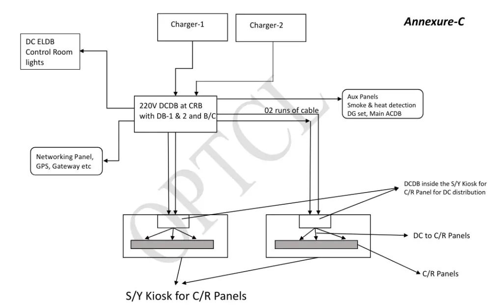
DC supply system in a substation consists of battery bank, battery charger, DC distribution board and control gear.Battery bank are either lead acid or dry cells type and battery charger used can float charge the battery while they are on load and it also has boost charging function.
Generally we use two DC battery banks and thus two battery chargers are used in order to have more reliable DC power. The batteries are placed in a battery room and they are connected to the distribution boards and battery charger are placed in either same or adjacent room .The charger are also connected to the load bus of DCDB through DC MCB. Also an emergency D.C. lighting board/system (also called Emergency Light Distribution Board) is also provided in each sub-station to operate a separate lighting system with D.C. power in case there is total failure of A.C. supply.
Two DC sources ,Source-01 and 02 are used for DC supply in a bay. A bay is a circuit which consists of Isolators,Circuit breaker,C.Ts ,Surge arresters etc and we can send or receive power using this circuit.There are broadly four kinds of bays, feeder bay (line bay) ,Transformer bay, Bus-coupler bay and Transfer bus-coupler bay.

Why do we use DC in a substation and its importance has been explained here.
DC Distribution drawing
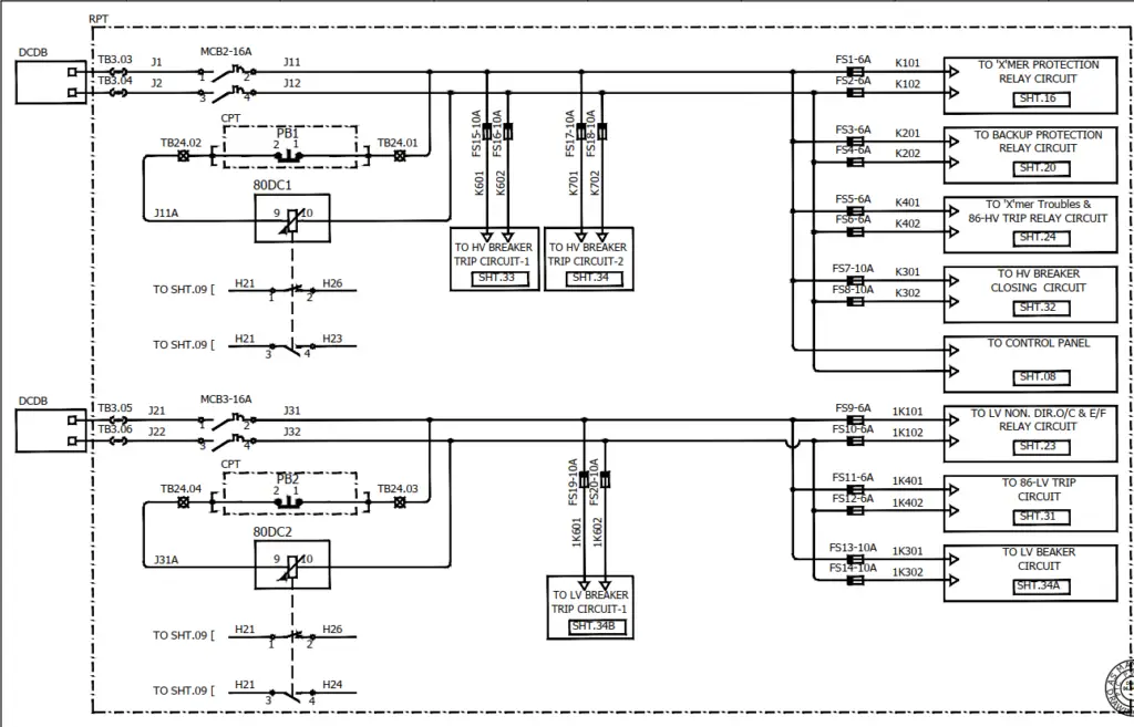
DC distribution in a bay is done using two separate DC sources of 220V DC. Below diagram is of DC distribution in a transformer panel, it explains how DC supply enters the control and relay panel and how they are distributed ahead.

(Pic- D.C distribution in a transformer bay)
From DCDB panel, two DC sources enter the Relay Panel side (RPT) at the TB Nos. as shown in above diagram. Two DC MCBs for each source are used in the panel and they have been named MCB-2 and MCB-3. Output side of MCBs is connected to 80 DC relays-01 ,02 and different fuses and through these fuses DC supply is carried ahead for different circuits as shown. In place of fuses ,MCBs can also be provided.
We use two DC sources for more reliability and to have one source in operation in case there is issue or some failure of the other source .In the drawing shown above source-01 is being used for HV side and source-02 is being used for LV side of the transformer. In some panel DC distribution scheme DC source-01 may be used to power Main relay and Source-02 for backup relay ,also source-01 for Trip coil ckt-01 and source-02 for trip coil ckt-02 may be used thus ensuring integrity as well as safety of the bay.
In order to rectify DC earth fault , we use this distribution diagram to understand how DC has been distributed in the Panel. It is quite evident from the above drawing that DC is required for Tripping, Closing,Indication and protection circuit of a bay.