Electrical insulators are materials or devices designed to block the flow of electric current. They serve as barriers, preventing the conduction of electricity between conductive materials. This is achieved through their unique property of high electrical resistance.
Types of Electrical Insulators
- Ceramic Insulators: These insulators, typically made of porcelain, are known for their excellent electrical insulating properties. They find extensive use in overhead power transmission lines and substations.
- Glass Insulators: Glass insulators are commonly used in telecommunication and transmission lines due to their high dielectric strength and durability.
- Polymer Insulators: These insulators are lightweight and exhibit remarkable resistance to environmental factors like pollution and UV radiation. They are often used in polluted or coastal areas. Ceramic (Porcelain) insulators are now being replaced with polymer due to its lightweight and less prone to damages. During flashovers , bursting of porcelain insulators can cause serious damage to a person nearby compared to a polymer insulator.
- Composite Insulators: These insulators combine the advantages of both polymer and glass insulators, offering high performance and resistance to contamination.
No.of discs required for different voltage level can be calculated using the formula given below:
Disc Insulator Formula
N =P KV /(√3 *11 KV )
N = number of Discs insulators
P KV = Value of voltage level
Bus Post Insulators:
It is a type of electrical insulator used to support and insulate busbars in power distribution and electrical substations. Busbars are conductive bars or systems that carry electrical current between various components of a power distribution system. Bus post insulators are essential for ensuring the safe and reliable operation of these systems. Bus post insulators are typically designed as a cylindrical or column-shaped insulating structure, often made of materials like porcelain, glass, or composite materials. They have a threaded stud or bolt at the top and bottom to secure them to the busbar and the supporting structure.
Applications of Electrical Insulators:
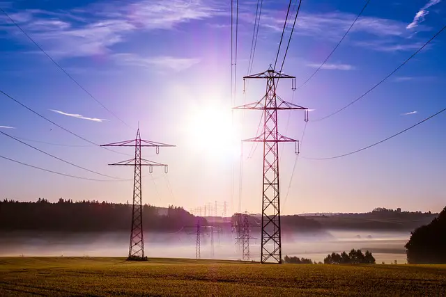
Overhead transmission lines carry power through conductors suspended on electric poles or transmission towers. These poles and towers have insulator strings attached to them and conductor are clamped to these insulator strings . It is done so that the current flowing in the conductor doesn’t flow in the poles or towers. These electrical towers are grounded so that when due to some fault (electrical or mechanical) the conductor touches the tower body, it gets grounded and the person or animal nearby doesn’t get electrocuted.

For an ideal insulator as the insulating material is 100 % pure, the current passing through the insulator should only have capacitive component and it should behave like a pure capacitor, but practically some amount of impurity is always there so there is also resistive component of current.
Causes of failure of Insulators:
One of the reason of failure of insulator is current leakage path created across it due to dust and pollution. This causes flashover, it is usually caused by transient high voltages and can be enhanced by air pollution and/ or humidity at the surface of the insulator. Any type of contaminant can cause insulation to fail. When pinholes and cracks occur, and contaminants get into those spaces, the insulation will begin to fail.
If the insulators are not kept clean, such buildup of pollutants will occur and it will result in a flashover. For this reason, workmen have to perform a “hot wash” by spraying the insulators with highly pressurized distilled water—which is, to most people’s surprise, nonconductive.
Testing of Insulators:
- Dielectric Strength Test: This test determines the maximum voltage an insulator can withstand without breaking down. It involves applying an increasing voltage until a breakdown occurs.
- Insulation resistance test: Test voltage is applied at both ends of insulator and readings are recorded. Values in Giga-ohm is considered good .
- Power Frequency Voltage Test: It assesses the insulator’s ability to withstand continuous operating voltage.
- Partial Discharge Test: This test identifies partial discharges that can lead to insulation failure over time.
- Flashover Test: It evaluates the insulator’s resistance to flashover, which is the unintended electrical discharge over the surface.
Pollution Testing
In areas with high pollution or salt contamination, insulators may be prone to surface leakage currents and pollution testing with help of some chemicals is also done. You may read more about it here.