Electrical power can be transmitted and distributed by either using insulated cables or by using overhead lines on electrical towers. Overhead lines are suspended on electric poles or electrical towers at a safer distance above the ground so that it has a safe clearance from the ground and there is no risk of electrocution or any hazard.
Height of towers and conductors from the ground depends on the voltage level being carried through it. Minimum electrical clearance has been explained here.
Electrical towers are also called transmission towers. Overhead transmission lines carry power through conductors and they are attached to electrical insulators which are suspended on transmission towers.
Parts of electrical towers
Electrical towers consists of the following parts:
- The peak of the transmission tower: Earth wire is placed on peak of the electrical towers.
- The cross arm of the transmission tower: Insulators are suspended on the cross arms.
- The boom of transmission tower
- Cage of transmission tower
- Transmission Tower Body
- Leg of transmission tower
- Stub and Baseplate assembly of the transmission tower: Stub is the starting part of the tower and it is directly attached to the tower foundation and from here other tower members are connected in the electrical towers.

There are several types of transmission towers, each designed for specific purposes and varying in their construction ,some common Electrical towers and its types are following:
- Suspension Towers: These are the most common type of transmission towers. These are used where transmission line moves in straight direction and deviation angle is zero to five degrees. The cross-arms of towers extend horizontally from the top. Towers shown in above image is of Suspension type. The power lines are suspended from insulators attached to the cross-arms. There is No jumper connection between the conductor in this type of tower. They are also called A type towers.
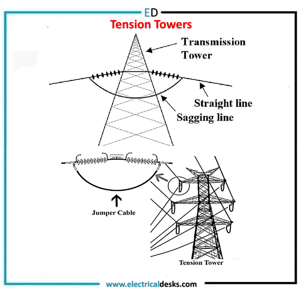
- Tension Towers: Tension towers are more strong compared to suspension towers. Theses are used where deviation angle of conductor span is more than five degrees.

(PC-Electricaldesks.com)
As shown in above pic, jumper connection is used in tension towers. Depending on angle of deviation they are classified as B,C and D type towers ,max deviation is for D type towers which is sixty degrees, if a transmission line is to be turned more than 60 degrees then special types of towers are constructed.
2 a) Dead-End Towers: Dead-end towers are tension towers ,they are usually D-type towers which are constructed at the ends of transmission lines just outside the boundary of substations where the line terminates.
3. Guyed Towers: Guyed towers are supported by guy wires or cables anchored to the ground. These towers are typically used for extra high voltage transmission lines or in areas where it is not feasible to build self-supporting towers. Emergency response towers (ERS) which are erected temporarily in case of emergencies like collapse of conventional towers are supported by anchors & guy wires.
4.Monopoles: Monopoles are single-pole structures made of steel or concrete. They can be constructed in smaller space compared to conventional towers ,therefore suited for cities and busy areas. They are freestanding and do not require any guy wires or support cables. Monopoles are commonly used in urban areas or locations with limited space.
5.Muti-circuit tower: It is usually used in those areas where there is space constraint .On muti-circuit towers more than 02 circuits of 03 phase transmission lines can be placed. Conventional towers have six cross-arms, three on each side and thus they can carry six conductors ,but multi-circuit towers can carry 12 ,18 or more conductors thus saving the need of construction of more conventional towers.