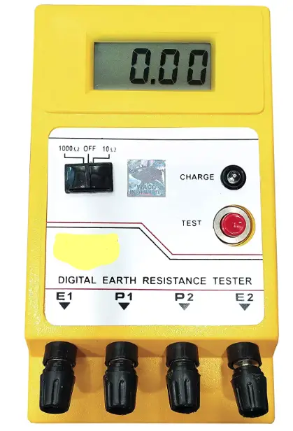
Digital Earth Tester

Digital Earth tester is used to measure earth resistance. Earth resistance refers to the impedance offered by the ground or soil to the flow of electric current. Its value is very important in electrical engineering, as it is directly related with safety of electrical systems, grounding systems for buildings, power distribution networks, lightning protection systems etc. Basically all our protection system will work well only when our grounding is perfect.
The resistance of the earth depends on several factors, including the composition and moisture content of the soil, the depth of the grounding electrode, and the surrounding geological conditions. Lower resistance values indicate better conductivity and are desirable for effective grounding and electrical safety.
How to use a Digital Earth Tester
All fault currents flow through grounding rods/earthing system , therefore they should provide a low resistance path to fault current. Measuring earth resistance is typically done using a measuring instrument called digital earth testers or ground resistance meters. These instruments apply a known voltage to the ground and measure the resulting current flow, it then allows for the calculation of the earth resistance based on Ohm’s law (R = V/I), where R is resistance, V is voltage, and I is current.
Ideally ground resistance should be zero ,but practically it is not the case. IEEE recommend a ground resistance value of 5.0 ohms or less to be acceptable values. Accurate measurement of earth resistance is necessary for ensuring the effectiveness of grounding systems, which provide a low-resistance path to dissipate fault currents and protect equipment and personnel from electrical hazards, such as electric shock and lightning strikes. Proper grounding also helps to maintain electrical system stability and minimize interference in sensitive electronic equipment.
Connection procedure of Digital Earth Tester
The most common method for measuring ground resistance uses the fall-of-potential principle of alternating current (AC) at higher frequency circulating between an auxiliary electrode and the ground electrode under test; the reading is usually taken in ohms and it represents the resistance of the ground electrode to the surrounding earth.
Soil Resistivity plays important role in determining the resistance of a grounding electrode , and to what depth it must be driven to obtain low ground resistance. The resistivity of the soil varies widely throughout the geographical area and it also changes seasonally. Soil Resistivity is determined largely by its content of electrolytes, consisting of moisture, minerals, and dissolved salts.
A dry soil has high resistivity if it contains no soluble salts. It figures has a direct impact on the overall sub-station resistance and how much earth electrode is required to achieve the desired values. Lower the resistivity, fewer the electrodes required to achieve the desired earth resistance value. Hence the Soil Resistivity is also important test.
Two terminals E/C( In some kit “E” is mentioned and in some “C” is mentioned) and P are provided in these testers. E/C is called current terminal and P is called Potential terminal.
1. E1and P1 are shorted with each other and connected with earth pit whose resistance is to be measured. E2 and P2 are connected to electrodes and buried in earth , P2 is buried at distance of 20m from E1 .E2 is buried 30 m from E1 and distance between P1 and P2 must be 61.8% of E1-E2
2. After the connection is made , test button in the kit is pressed which injects the voltage and resistance value is displayed.
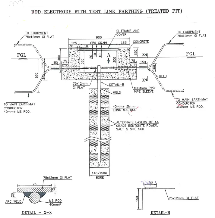
Earth pit construction drawing :

In one of the earthing design perforated pipe is used for constructing earth pit, perforated pipe means it is designed with small slots or holes to allow water to exit or enter easily. This type of pipe is suited due to its ability to absorb and drain water.
Click here to read about Star point in a current transformer.