Network Theorems can be applied to D.C as well as an A.C. system, with the only difference that impedances replace the ohmic resistance of D.c. system.
Two Basic Network Theorems are :
1. Kirchhoff’s Current Law (KCL)
It states as follows : In any electrical network, the algebraic sum of the currents meeting at a point (or junction) is zero. It implies that total current leaving a junction is equal to the total current entering that junction. We assume the incoming currents to be positive and the outgoing currents as negative.

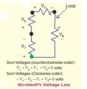
2.Kirchhoff’s Mesh Law or Voltage Law (KVL)
The algebraic sum of the products of currents and resistances in each of the conductors in any closed path (or mesh) in a network plus the algebraic sum of the e.m.fs. in that path is zero. In other words, Σ IR + Σ e.m.f. = 0

Independent and Dependent Sources
Those voltage or current sources, which do not depend on any other quantity in the circuit, are called independent sources .For example, a battery is an independent source. The independent current sources are also classified into two types :
Constant Current Source : An independent current sources whose output current remains constant throughout its operation is known as a constant independent current source. It is also known as time invariant current source.
Time-Variant Current Source : An independent current source whose output current changes time is referred to as a time variant independent current source.
A dependent voltage or current source is one which depends on some other quantity in the circuit which may be either a voltage or a current. Such a source is represented by a diamond-shaped symbol. There are four types of dependent sources, which are categorized by their controlling and controlled parts: Voltage-controlled voltage sources (VCVS), Current-controlled voltage sources (CCVS), Voltage-controlled current sources (VCCS), and Current-controlled current sources (CCCS).
Below mentioned network theorems are taught in engineering programmes and often require knowledge of basic network theorems like KCL and KVL as explained above.
1.Superposition Theorem
It is important to keep in mind that this theorem is applicable only to linear networks where current is linearly related to voltage as per Ohm’s law. It should be noted that the superposition theorem does not apply to power, as power is not a linear quantity.
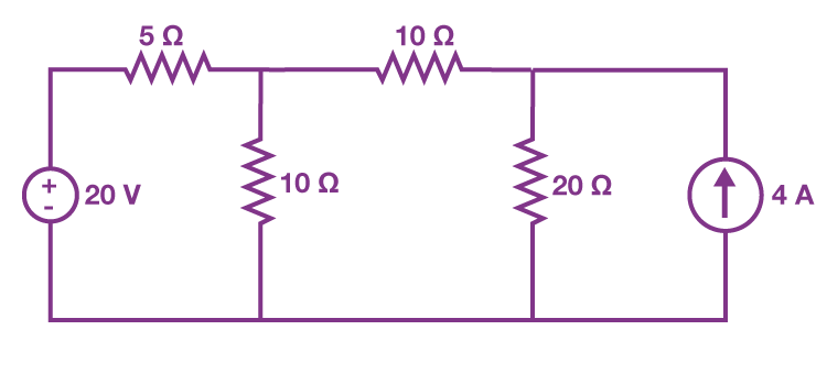
The theorem states that : In a network of linear resistances containing more than one generator (or source of e.m.f.), the current which flows at any point is the sum of all the currents which would flow at that point if each generator where considered separately and all the other generators replaced for the time being by resistances equal to their internal resistances.
In other words, the value of current in any conductor is the algebraic sum of the currents due to each e.m.f. Similarly, voltage across any conductor is the algebraic sum of the voltages which each e.m.f would have produced while acting singly. In other words, current in or voltage across, any conductor of the network is obtained by superimposing the currents and voltages due to each e.m.f. in the network.

When replacing the power supplies in the circuits, we must follow these two rules:
a) Replace all current sources with open circuits (breaks)
b) Replace all voltage sources with short circuits (wires)
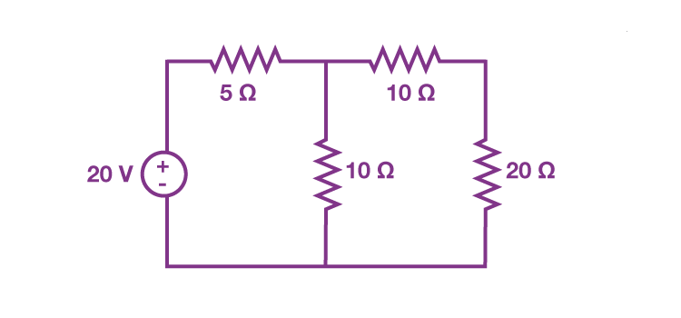
In first step let us consider current flowing through a circuit by considering only the 20 V voltage source. The current source can be open-circuited, hence, the modified circuit diagram is shown in the following figure :

In second step we calculate current flowing through the 20 Ω resistor to due 20 V voltage source is 0.4 A.(I1)
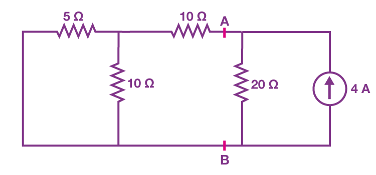
In third step: We find out the current flowing through the 20 Ω resistor considering only the 4 A current source. We eliminate the 20 V voltage source by short-circuiting it

Current flowing through the circuit when only 4 A current source is 1.6 A (I2)
In last step : The summation of currents I1 and I2 will give us the current flowing through the 20 Ω resistor.
I = 0.4+1.6 = 2 A
2.THEVENIN’S THEOREM
Thevenin’s theorem states that any two terminal linear network having a number of voltage and current sources and resistances can be replaced by a simple equivalent circuit consisting of a single voltage source called Thevenin’s voltage (VTH) in series with a resistance called Thevenin’s resistance (RTH), where the value of the Thevenin’s voltage source is equal to the open circuited voltage across the two terminals of the network and Thevenin’s resistance is equal to the equivalent resistance measured between the terminals.

It provides a mathematical technique for replacing a given network, as viewed from two output terminals, by a single voltage source with a series resistance. It makes the solution of complicated networks (particularly, electronic networks) quite quick and easy. The application of this extremely useful theorem will be explained with the help of the following simple example.

Steps to apply Thevenin’s Theorem:
- Remove the load resistor (the component across which we want to find voltage/current) from the circuit.
- Find the Thevenin equivalent voltage (Vth):
- Calculate the open-circuit voltage across the terminals where the load was connected. It is also called ‘Thevenin voltage Vth. Replace the entire network by a single Thevenin source, whose voltage is Vth or Voc and whose internal resistance is Rth or Ri.
- Calculate the open-circuit voltage across the terminals where the load was connected. It is also called ‘Thevenin voltage Vth. Replace the entire network by a single Thevenin source, whose voltage is Vth or Voc and whose internal resistance is Rth or Ri.
- Find the Thevenin equivalent resistance (Rth):
- Deactivate all independent voltage and current sources (replace voltage sources with short circuits or internal resistance if given and current sources with open circuits).
- Calculate the equivalent resistance seen from the terminals where the load was connected. This resistance is also called Thevenin resistance Rsh.
- Re-attach the load resistor:
- Once the Thevenin equivalent circuit is formed, reconnect the load resistor.
- Solve the simplified circuit to find the current or voltage across the load resistor using basic Ohm’s law or voltage division.Finally, calculate the current flowing through RL by using the equation,

This theorem is valid even for those linear networks which have a nonlinear load.