Star point in a Current transformer decides the direction in a directional relay as well as energy meter import/export direction. Star Point in a Current transformer (S1,S2,S3 etc) is chosen as per following conditions and requirements:
a) Physical placement of the C.T
b) Orientation of the element to be protected w.r.t C.T and
c) Desired C.T ratio.
P1,P2 are Primary side terminals of C.T and S1,S2,S3 etc are secondary terminals of C.T. Star point (S1 or S2 or S3 etc) is looped in all Phases R,Y and B and grounded either in Current transformer junction box or in control & relay panel. This has been explained below.
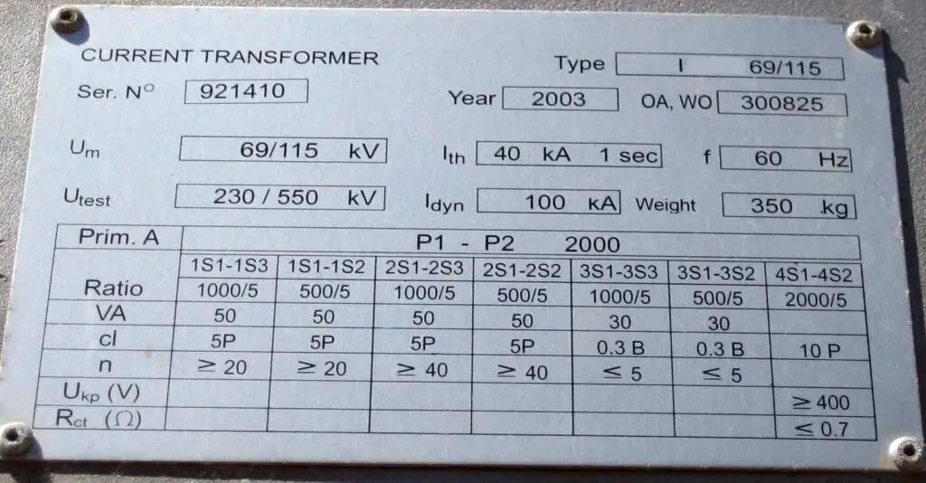
Name plate of a Current transformer reveals information about current rating, number of cores and whether they are protection or metering core, also drawing is provided for primary and secondary connections to be made for different current ratio etc.
How S1 is made Star Point in a Current transformer
S1,S2,S3 etc are secondary output of a C.T and they are used for making different C.T ratio as well as for making star point. From the name plate of C.T shown below it can be seen that all secondary current value is 5A, it means that it has secondary output current of 5A for primary current of 2000/1000/500A and it is a four core C.T (1-4). Secondary output current in a C.T is usually 1A or 5A. Star Point in a Current transformer is decided by physical orientation of Primary terminals-P1 and P2 of a C.T , orientation of the element to be protected and the desired C.T ratio.
If P1(Primary terminal) of a C.T is towards the element to be protected (feeder, transformer) then S1 is made the Star point in a Current transformer and if P2 terminal of a C.T is towards the element to be protected then any secondary terminal S2,S3,S4 etc can be made star point in a Current transformer depending on the desired C.T ratio except S1.
Multiple Cores in the C.T are basically parallel connections ,its advantage has been explained here. Unused cores in the C.T are grounded.

Kindly see in the above name plate:
1S1,1S2,1S3 are secondary terminals of first core similarly 2S1,2S2,1S3 are secondary terminals of second core and so on. Some cores in the CT are protection core and some are metering core. We connect protection relays with protection core of a Current transformer and energy meter is connected with metering core. Above C.T can be connected for different C.T ratio such as 1000/5,500/5 and 2000/5. “CL” mentioned in the above name plate is Class.
From the above shown Current transformer, suppose we need 1000/5 C.T ratio for some relay then protection core (05P) of C.T will be used .Let us understand its connection :
In 1st core for getting ratio of 1000/5, we can take output from either 1S1 or 1S3. If S1 is made star point ,output will be taken from 1S3. Similarly for getting ratio of 500/5 we can output from either 1S1 or 1S2.
If we need to make S1 as star point then following connections needs to be made in the C.T junction box:
We can use 1st core for 1000/5 C.T ratio as it is also a protection core. Please note that 1000/5 connection can be made by either taking output from S1 or S3. Since S1 is to made star point , then 1S1 of R,Y and B phase C.T needs to be looped and grounded and from 1S3 of each phase R,Y and B output to relay connection will be made.

Grounding of star point can be done either in Current transformer junction box which is located in the switchyard itself or in the Control and relay panel. It is to be noted that grounding is to be done at only one point either in junction box or in panel. Using the above we drawing we can now change C.T ratio as per our requirement and make connections accordingly.
How S2 is made a star Point in a Current transformer
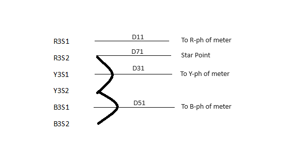
Now Let us make S2 as Star Point in above Current transformer for C.T ratio 500/1 and lets suppose it to be used for metering purpose. Please observe in the CT name plate, either 3S1 or 3S2 can be used for CTR of 500/1 in the metering core. Also as S2 is to be made star point then 3S2 of R,Y and B-phase needs to be looped with each other and grounded. Output to the energy meter will be taken from 3S1 of R,Y and B-phase. Its connection diagram will be done as following :

All fault current flows through the star point and therefore it is necessary that it is properly tightened and grounded. As S2 has been made a star Point in a Current transformer, in a similar way S3,S4,S5 etc can also be made star point depending on desired C.T ratio.