Introduction

(PC-https://www.industrybuying.com/)
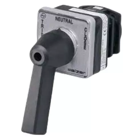
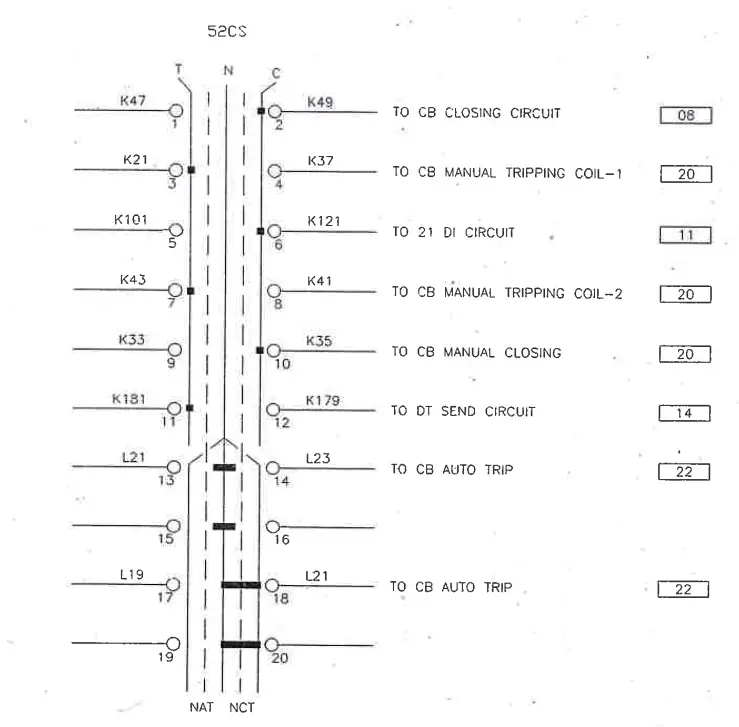
TNC Switch (Trip and close switch) as the name indicates is used to manually trip and close the circuit breaker. The three positions in the TNC switch wiring diagram as shown below are called Trip, Neutral and close. There are some NO (Normally open) contacts, some NC (Normally close) contacts and some spare NO and NC contacts given in a TNC switch.
First let us understand NO and NC contacts:
NO (Normally Open) Contacts in TNC Switch
NO, or Normally Open, contacts refer to a type of electrical contact that remains open in its normal state. This means that when no external force or signal is applied, the circuit connected to the NO contact remains open, and no current flows through it. However, when an activating force or signal is applied, such as pressing a button or activating a switch, the NO contact closes, allowing electricity to flow through the circuit.
NO contacts are commonly used in various applications, such as push-button switches, relay circuits, and control systems. They are often employed in situations where a circuit needs to be activated or closed to initiate a particular function or operation.
NC (Normally Closed) Contacts in TNC Switch
On the other hand, NC, or Normally Closed, contacts are the opposite of NO contacts. In their normal state, NC contacts are closed, allowing current to flow through the circuit connected to them. When an activating force or signal is applied, such as pressing a button or activating a switch, the NC contact opens, interrupting the flow of electricity through the circuit.
NC contacts find widespread use in applications where safety and fail-safe operation are paramount. For example, they are commonly utilized in emergency stop buttons, safety interlocks, and alarm systems. By default, NC contacts ensure that a circuit remains closed and operational until an external action triggers them to open, thereby halting the flow of electricity and initiating a safety measure or alarm.
Wiring diagram

Ferrules in the left are input side of TNC switch and ferrules on the right are output side of the switch. We have explained regarding ferrules here. K and L ferrules are DC supply ferrules ,where K ferrule is used for control circuit and L ferrule is used for alarm circuit.
It is to be noted that DC +Ve supply for tripping or closing the circuit breaker is taken from breaker itself.
K21 and K37 : CB Manual tripping coil 1
Positive DC supply is taken from circuit breaker and it then enters the control panel at some T.B (terminal block) and K21 is the input side of TNC switch when TNC switch is moved from neutral position towards trip position, contact is made between position no.03 and 04 of this switch and thus DC +Ve supply is extended through the switch through ferrule K37. Due to the Spring Action in the switch, it automatically comes back to Neutral Position from trip position.
As tripping and closing coil are supplied -Ve DC supply at all times, thus as soon as +Ve supply reaches through K37 to the tripping coil ,the coil gets energized and trips the breaker.
The wiring scheme of CB Manual tripping coil 2 and CB Manual closing will be analogous to TC1.
Spare NO and NC contacts are provided as TNC switch sometimes get faulty and it may extend power without moving the switch to trip and close position. Sometimes spring in the switch which brings back the switch to neutral position from trip and close position can get defective and the switch may get stuck and thus it can extend continuous closing or tripping command to the breaker which is not desirable.
To avoid continuous closing command to the breaker Anti Pumping relay is used.The anti-pumping relay is a NO (Normally Open) contact in its operational state. It means that the relay will be in the NO condition when the circuit breaker is in the closed state and the relay will be in the NC (Normally Closed) condition when the circuit breaker (CB) is in the open state condition.