PLCC-Power line carrier communication is used for telecommunication between substations, it is also used for tele-protection and conductors of transmission lines are used for these purpose. It is usually used for high voltages, such as 132 kV, 220 kV, 400 kV etc.
Two substations are connected using transmission lines (conductors) and these conductors are also used for establishing communication as well as protection of the lines. By using Power line carrier communication (PLCC) , substations have their own communication system and they don’t have to solely rely on mobile/other network for exchanging information. Speech +Data+Protection is made available in the substations with the help of PLCC.
Power line carrier communication (PLCC) Components:
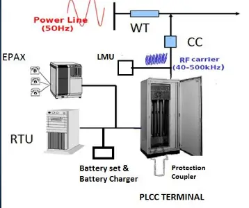
Following equipment are used for Power line carrier communication (PLCC )
- Capacitive Voltage transformer : A capacitive voltage transformer operates on the principle of capacitive voltage division. It consists of a series capacitor connected in the high voltage circuit and a capacitive voltage divider .
CVT with wave-trap is used in Power line carrier communication ,for filtering of communication signal from power signal & Substations also communicate with each other through this channel, they are also used for protection of lines. If one end of transmission line trips, other end gets also tripped by PLCC protection scheme. CVT also serve as coupling capacitors for coupling high-frequency power line carrier signals to the transmission line.
2. Wave or Line Traps : A wave trap looks like a big basket (usually off white in color) which are suspended on gantry beams or installed on its own foundation in a substation .They are basically a coil having high inductance.The wave trap is used along with a coupling capacitor or a capacitor voltage transformer (CVT) both of which possess high capacitance value for PLCC.
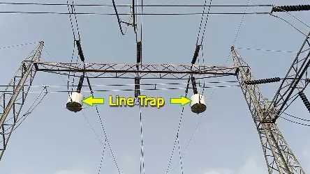
As the communication circuit works on High frequency in the range of kilo/mega hertz value. So there is no chance of interference or cross over between electrical and communication signal.
Wave traps are also known as a high-frequency stopper, its a device which function is to block high-frequency communication signals, approximately ranging from 30 to 500 kHz.Wave trap acts as a LPF(low pass filter) which allows the Power Signal to pass through it but blocks the Communication Signal.
3. Line Matching Unit (LMU)
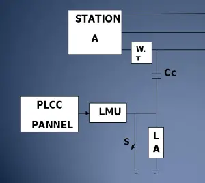
A line matching unit is used to match the impedance of the PLCC equipment to the impedance of the transmission- line. Line Matching Units is a composite unit which consists of Drain Coil, Isolation transformer with Lightning Arrestor on its both the sides, a Tuning Device and an earth switch. A Tuning Device is a combination of R-L-C circuits which act as filter circuit. LMU is also known as Coupling Device.
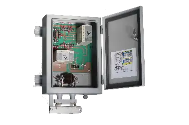
Together with coupling capacitor, LMU serves the purpose of connecting effectively the Audio/Radio frequency signals to either transmission line or PLCC terminal and protection of the PLCC unit from the over voltages caused due to transients on power system.
It ensures that the signals are transmitted with minimal loss and distortion, resulting in improved signal quality and less noise interference.
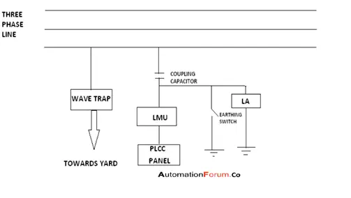
(Connection Diagram , PC-Automationforum.co)
Coaxial cable is used for interconnection between PLCC and LMU.A Coaxial cable is used as a transmission line for radio frequency signals.
4. Earth switch
This switch as shown in the above picture is used while doing maintenance of LMU or before inspection of LMU, one must close this switch so that the power signal gets grounded.
Types of coupling in PLCC
A.Phase to ground coupling
In this type of coupling-out of three phase ,we use only one conductor for communication and the wave/line traps and coupling capacitors are all connected to this conductor of the transmission line .
(B) Phase to phase coupling
In this type of coupling-out of three phases, we use two phases for communication and the advantage of this coupling is that if one route is damaged then communication will take place by another path.
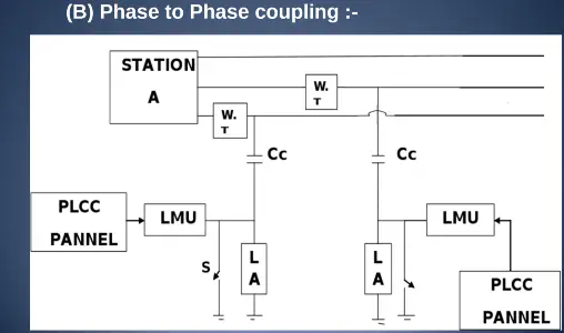
If the coupling is Phase-Phase it requires LMU & LMDU (Line matching double unit). If the coupling is Phase-Ground LMU is enough for Power Line Communication.
It is to be noted that PLCC works on 48v DC power supply. Therefore battery bank and charger are also installed for this purpose.
Testing and Commissioning
For Testing and Commissioning of PLCC following is checked:
> When carrier send/receive command is given in the PLCC panel in one end, the other end should receive the same.
>When DT(Direct trip) send/receive command is given in the PLCC panel in one end, the other end should receive the same and trip the breaker.When one end of breaker is even tripped manually the other end should also trip.
>The Signal level is checked using a signal level meter and it is ensured that adequate signal level are present in sending end and there is very less signal loss.
These days PLCC systems are being replaced with new technology using OPGW (Optical ground wire) and in place of normal earth wires ,Optical ground wire are being strung on transmission towers which serves dual purpose of protecting the conductors from lightning and optical fibres in them are used for Data, speech and protection between substations.
OPGW(Optical ground wire)
An optical fiber composite overhead ground wire is a type of cable that is used in overhead transmission lines. Such cable performs two functions ,one that of grounding and other of communications. An OPGW cable contains a tubular structure with one or more optical fibers in it, and this is surrounded by layers of steel and aluminum wire.
The optical fibers within the OPGW cable can be used for high-speed transmission of data, speech and protection and control of the transmission line, or the fibres can be leased or sold to third parties to serve as a high-speed fiber interconnection between cities which can be used for broadband internet connection. For protection of lines through OPGW, we use Digital Protection Coupler (DTPC) for tripping of lines.
Digital Protection Coupler
The Digital protection signalling equipment transfers the trip commands from one end of the line to the other end in the shortest possible time with adequate security and dependability. It also monitors the healthiness of the link from one end to the other and give alarms in case of any abnormality.
Principle of operation: When Protection signalling equipment is actuated by protective relays for transmission of commands, it interrupts the guard signal/code and it will transmit the command code to the remote end. The receiver end recognizes the command code and absence of the guard code and it then generates the command to the protective relays.