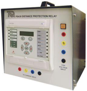
Distance Protection relay is a key component of electrical protection systems. It acts as a guardian, ensuring the power grid remains functional even in adverse conditions. Distance relay specifically focuses on the impedance of a transmission line and it is directional in nature. It plays a pivotal role in protecting power lines from faults, such as short circuits and overloads, thus isolating the faulty part from the system and hence maintaining the reliability of the overall system. The impedance of a transmission line or power system varies with distance. Distance relays are designed with characteristic curves that represent the expected impedance for different distances from the relay location.
How Distance Protection Relay Works
Distance Protection relays work based on the principle of measuring the impedance (or the apparent electrical resistance) between the relay location (substation) and the fault point. Here’s an overview of how distance relays work, including their basic principles:
Impedance Measurement:
- Distance Protection relays continuously monitor the electrical impedance between the relay location and the fault point. The impedance is a combination of the resistance (R) and reactance (X) of the electrical circuit.
Zone of Protection:
Distance Protection relays are typically classified into several zones, each with its own impedance reach, and the zones are often labeled numerically or descriptively, such as Zone 1, Zone 2, and Zone 3. Here’s an explanation of these zones:
Zone 1: Forward Reach Zone:
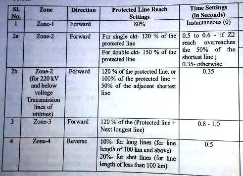
- Zone 1 is the closest to the relay location and provides the primary and fastest protection coverage. It is generally 80% of the protected line length. Protected line length is the line in which distance protection relay is being used.
- It is designed to detect faults very close to the relay (up to the reach of Zone 1).
- Zone 1 provides high-speed protection to quickly clear faults near the relay to prevent damage and minimize system disturbances.
Zone 2: Time-Delayed Zone:
- Zone 2 covers a larger distance beyond Zone 1, typically reaching farther into the protected transmission line.
- It provides secondary protection, allowing for a time delay before tripping the circuit breaker.
- The time delay ensures selectivity, meaning that Zone 2 will only trip if Zone 1 doesn’t respond.
Zone 3: Remote Backup Zone:
- Zone 3 is the outermost protection zone, covering the farthest portion of the protected line.
- It offers backup protection and typically has longer time delays than Zone 2.
- Zone 3 is designed to clear faults outside the reach of Zones 1 and 2, ensuring that even more remote faults are eventually cleared.
Zone-04: In this zone fault is sensed in the reverse direction up to 10% of the protected line.
General Zone setting is following:

The use of multiple zones allows for a coordinated and selective protection scheme. Each zone operates with a specific time-delay characteristic, and as faults occur, the relay compares the fault impedance to the impedance settings for each zone. The relay operates when a fault falls within the specified zone and the defined time-delay criteria are met. This layered approach ensures that the relay only responds to faults within its coverage area and avoids unnecessary trips for external faults.
The settings for each zone, including the reach and time delay settings, are carefully configured to balance protection coordination and coverage. Zone settings depend on factors such as the length of the transmission line, the desired protection selectivity, and the need to minimize power system disturbances. Proper coordination of these zones is essential for efficient and reliable protection of the power system.
Characteristic Curve:
- Distance Protection relays typically use a characteristic curve to determine when a fault occurs. This curve defines the relationship between the measured impedance and the time delay before tripping the circuit breaker. The curve can be set based on the specific requirements of the protected circuit.
Fault Detection
- If the measured impedance falls within a predefined zone on the characteristic curve, the relay initiates a tripping signal to open the circuit breaker associated with the protected section.
- The tripping action is intended to isolate the faulty part of the power system, preventing further damage and maintaining the reliability of the overall system.
- When a fault occurs, such as a short circuit or a line fault, the impedance in the line changes. This altered impedance value is detected by the relay.
Comparison with Zone Settings:
- The relay compares the detected impedance to its predetermined zone settings.
- If the impedance falls outside the defined protection zone (i.e., the fault is outside the zone of protection), the relay takes no action. If the fault occurs within defined protection zone then fault location ,fault impedance, fault current data etc are recorded and it is displayed in the relay. These data are very important for analysis of fault as well as for rectification of fault. If the distance of occurrence of fault becomes known, it becomes very convenient to physically reach the place of fault and check for visual faults and take necessary actions accordingly.
Tripping the Circuit Breaker:
- If the detected impedance falls within the defined protection zone, it indicates a fault within the relay’s coverage area.
- The relay initiates a trip signal to open the circuit breaker associated with the protected area.
- The circuit breaker’s opening action isolates the fault, preventing further damage to the power system.
Key Features and Considerations:
1.Distance Protection relays are directional, meaning they can determine the fault location based on the phase relationship of currents and voltages.
2.The relay settings, including reach and characteristic curve, need to be carefully configured to balance protection coverage and selectivity (i.e., ensuring that the relay operates only for faults within its designated zone).
3.These relays are commonly used for protecting transmission lines and feeders, where knowing the fault location is essential for minimizing service interruptions.
4.Distance relays are more suitable for radial power systems with a single source. In meshed networks, more complex protection schemes are often employed.
5.They are a part of a broader protection and control system, often working in conjunction with other protective relays, such as overcurrent and differential relays.
In addition to distance relays we also have offline distance fault locator. Its an equipment which can detect the type of fault whether open or ground and also indicate the phase of fault in which this fault has occurred.But it can be only used when the line is not energized, hence the name offline distance fault locator.